
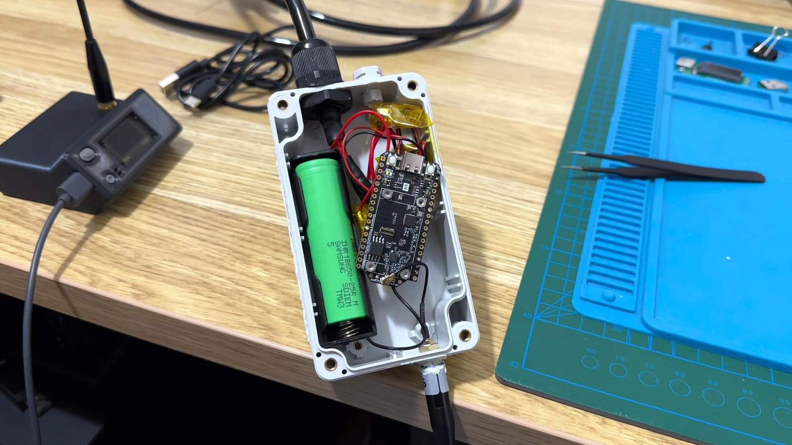
Monitoring the water level in a rainwater tank seems like a fairly simple smart home project, but my previous attempts showed me there are a few problems to solve if the tank is any real distance from the house.
I had already built Wi-Fi versions of my tank sensor, and while they worked, Wi-Fi wasn’t really ideal for this job. Range was one problem, especially once the sensor was moved further away from the house. Battery life was the other.
Keeping an ESP32 connected to Wi-Fi, even intermittently, used more power than I wanted from something that was supposed to live outside and mostly be forgotten about.
For this version I decided to move away from Wi-Fi completely during normal operation and use LoRa instead.
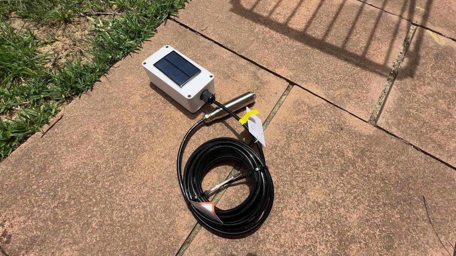
The result is a solar-powered, battery-backed LoRa water tank sensor that measures the depth of the water using a submersible pressure sensor, sends the reading over LoRa to a gateway and then makes the data available in Home Assistant through MQTT.
There is no LoRaWAN network involved and the tank sensor itself doesn’t need Wi-Fi coverage.
How the LoRa Tank Sensor Works
The basic idea is fairly simple.
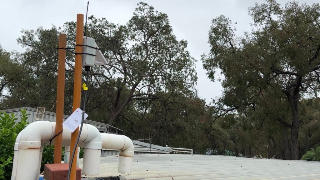
A pressure sensor sits at the bottom of the tank and produces an analogue voltage that changes depending on the depth of the water above it.
A Heltec V4 reads that voltage, converts it into a water depth and tank percentage, then sends the results over LoRa.
Inside the house, my LoRa gateway receives the transmission and publishes the readings to MQTT. Home Assistant then picks them up automatically using MQTT Discovery.
The tank sensor doesn’t stay powered up and running all day. Most of the time it is in deep sleep.
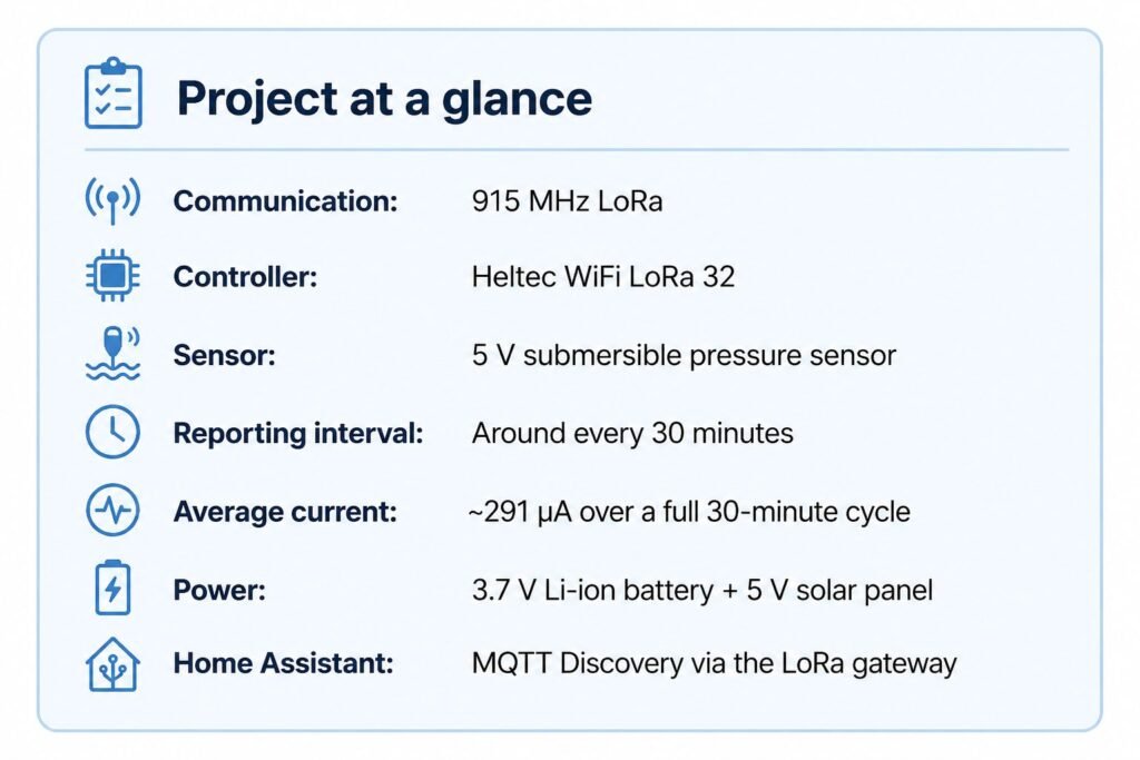
Roughly every 30 minutes it wakes up, powers the pressure sensor, takes a measurement, sends the results to the gateway, waits for an acknowledgement and then goes back to sleep.
That makes LoRa a much better fit for this project than Wi-Fi.
Why I Switched From Wi-Fi to LoRa
I’ve built Wi-Fi water tank sensors before, so using Wi-Fi again would have been the easiest option.
The problem was that it didn’t really suit where I wanted to take the project.
My earlier versions consumed more battery than I wanted and Wi-Fi coverage became unreliable once the tank was further from the house. I could have added another access point or extended the Wi-Fi network, but that felt like solving the wrong problem.
The sensor only needs to send a tiny amount of information every half hour. It doesn’t need the bandwidth of Wi-Fi.
LoRa is designed for exactly this sort of communication. You trade data speed for considerably better range and low power operation.
For a tank level reading consisting of a few numbers, that’s a trade I’m very happy to make.
The sensor also doesn’t need to join the home’s Wi-Fi network at all during normal operation. As far as it is concerned, it only needs to be able to communicate with the LoRa gateway.
The gateway handles Wi-Fi, MQTT and Home Assistant.
LoRa, But Not LoRaWAN
One thing worth clearing up is that this project uses LoRa, not LoRaWAN.
LoRa is the radio technology being used to send the data.
LoRaWAN is a complete networking protocol built on top of LoRa, normally involving gateways, network servers and a larger network infrastructure.
I didn’t need any of that here.
I’m only trying to move small amounts of data between sensors around a property and one gateway, so I built a much simpler private LoRa network instead.
That means there is no external LoRaWAN service, no cloud account and no LoRaWAN network server involved.
The tank sensor talks directly to my gateway.
Parts I Used
This is the hardware used for my current tank sensor.
| Component | What I’m using it for |
|---|---|
| Heltec WiFi LoRa 32 V4.3 | Main controller and SX1262 LoRa radio |
| 5V submersible pressure sensor with 0 to 3.3V output | Measures water depth |
| TPS61023 boost converter | Boosts the battery voltage to 5 V for the pressure sensor |
| 3.7V Li-ion battery | Stores power for the sensor |
| 5V solar panel | Keeps the battery charged |
| 1S battery protection/BMS board | Battery protection |
| 915 MHz LoRa antenna | LoRa communication |
| 100 kΩ resistor | Pulls the TPS61023 enable pin low when required |
| Waterproof enclosure and cable glands | Keeps the electronics protected outdoors |
The pressure sensor was one of the main things that influenced the rest of the design.
It requires a 5V supply but outputs an analogue signal between approximately 0 and 3.3V.
That means its output can be connected to the ESP32 ADC, but I still need to generate a 5V supply for the sensor itself.
That’s what the TPS61023 is doing.
Powering the Pressure Sensor
I didn’t want the pressure sensor and 5V boost converter running continuously.
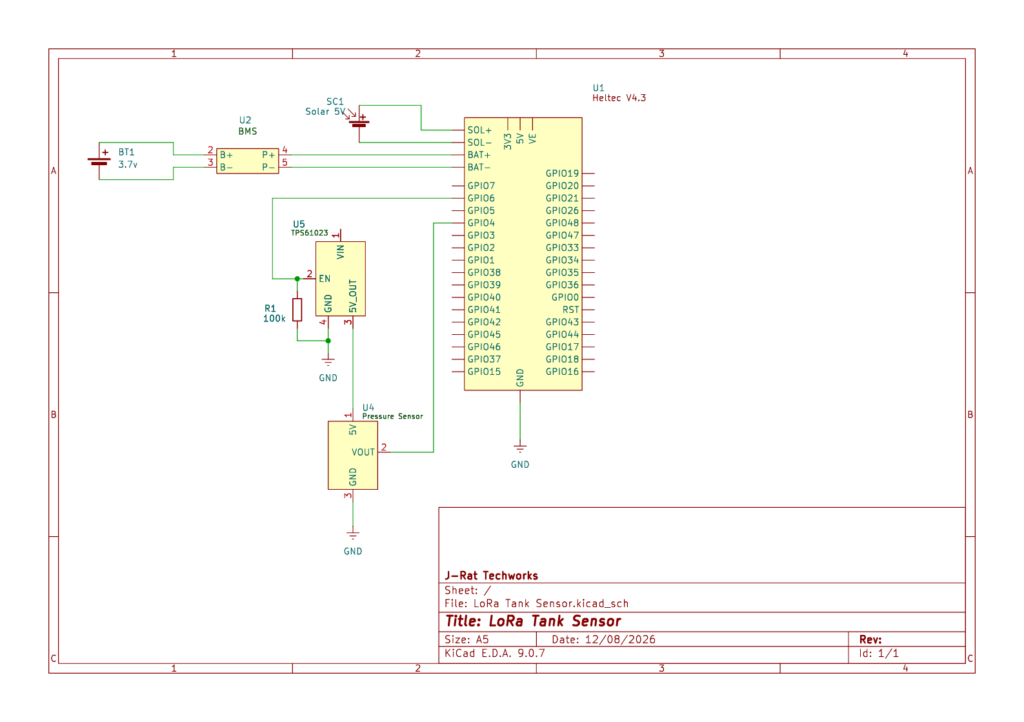
Instead, the Heltec controls the enable pin on the TPS61023.
In my current build:
Pressure sensor signal: GPIO 4
TPS61023 enable: GPIO 6
When the tank sensor wakes up, GPIO 6 enables the boost converter. The TPS61023 then supplies 5V to the pressure sensor.
The code waits for the sensor to stabilise before taking a number of ADC samples. Once the measurement is complete, the boost converter is switched off again.
This means the pressure sensor isn’t sitting there drawing power for the entire 30 minutes between readings.
It’s only powered when I actually need it.
Why I Used a Pressure Sensor
There are a few different ways you can measure the level of water in a tank.
Ultrasonic sensors are probably one of the most common DIY options. Mount one at the top of the tank, measure the distance down to the surface of the water and calculate the level from there.
I’ve used that approach before, but for this version I wanted to try a submersible pressure sensor.
The pressure sensor sits at the bottom of the tank. As the water level rises, the pressure created by the water above the sensor also increases.
From that measurement I can calculate the approximate water depth.
There are a few advantages to doing it this way. I don’t have to worry about the shape of the roof of the tank, reflections from the sides or getting a clean ultrasonic reading from the surface of the water.
The downside is that the pressure sensor needs to be calibrated properly.
Fortunately, I’ve now built that into the firmware as well.
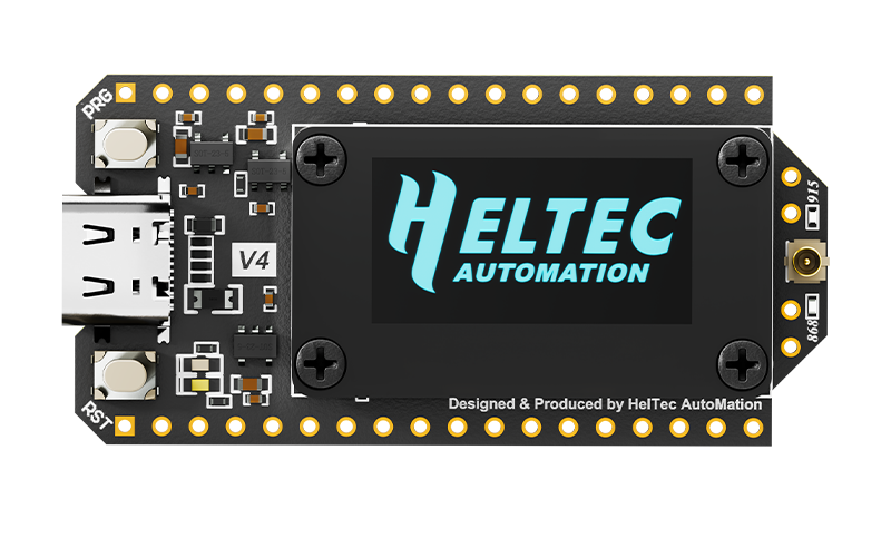
Heltec V4
I used the Heltec V4 because it combines the ESP32-S3 and SX1262 LoRa radio on one board, which keeps the overall sensor build relatively compact.
Calibrating the Tank Sensor
This is one part of the project that I wanted to make much easier than my original prototypes.
Early versions had calibration values entered directly into the code.
For my own tank that was fine, but it isn’t particularly friendly if someone else wants to build the project. Their tank won’t necessarily be the same height and their pressure sensor probably won’t produce exactly the same voltage as mine.
The current firmware has a calibration portal built into the tank sensor.
To access it, I reset the sensor and then hold the PRG/BOOT button for a couple of seconds during startup.
The sensor temporarily enables Wi-Fi and creates its own setup network.
After connecting to that network, the calibration page can be opened in a browser.
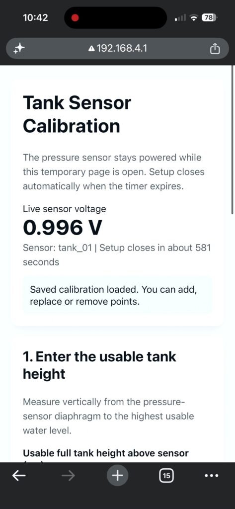
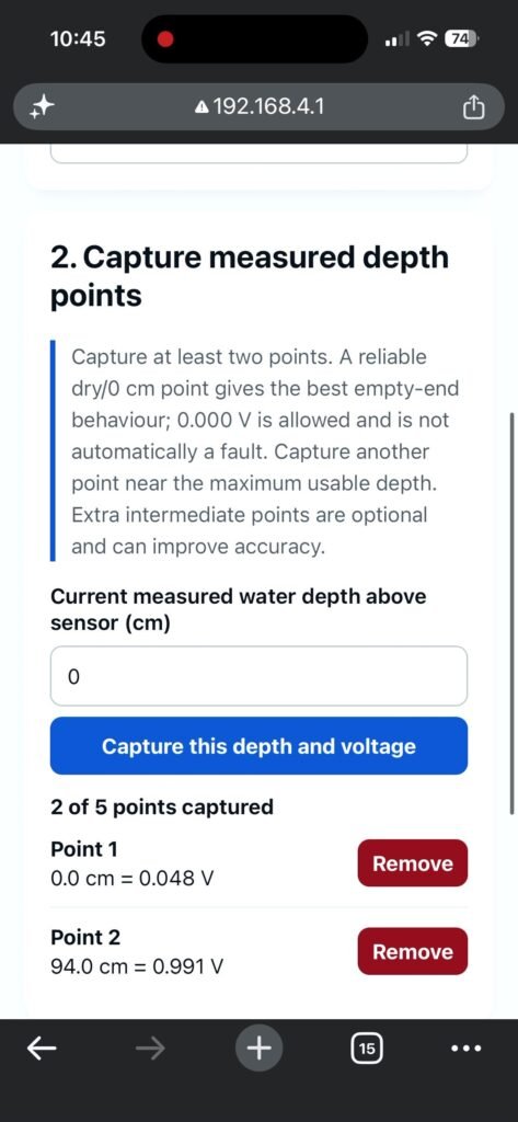
From there I can capture actual pressure sensor readings at known water depths and enter the usable height of the tank.
My own original three calibration points were:
| Water depth | Pressure sensor voltage |
|---|---|
| 0cm | 0.048V |
| 94cm | 0.991V |
| 200cm | 2.050V |
My tank has a usable height of approximately 200 cm.
Rather than assuming that the pressure sensor is perfectly linear according to its advertised specification, the code can interpolate between measured calibration points.
Once the calibration has been saved, it is stored in the ESP32’s non-volatile memory. It survives normal resets, deep sleep and a complete loss of battery power.
Wi-Fi is then turned back off before normal sensing resumes.
So although the Heltec has Wi-Fi, it isn’t being used every time the tank sends a reading. I’ve kept it specifically for local setup and calibration where it is actually useful.
What Happens Every Time the Sensor Wakes Up
The main firmware cycle is deliberately quite short.
The sensor wakes from deep sleep and checks its saved configuration. It then powers the pressure sensor through the TPS61023 and waits briefly for it to settle.
Rather than trusting one ADC measurement, the firmware takes several samples and uses them to get a more stable reading.
The measured voltage is then converted into water depth using the saved calibration points.
From the water depth, the sensor can calculate the percentage of the usable tank height currently filled.
The battery voltage is also measured.
Once the reading is ready, the sensor sends the data to the gateway over LoRa.
If everything goes to plan, the gateway replies with an acknowledgement.
The pressure sensor, radio hardware and other unnecessary parts of the board are then shut down before the ESP32 enters deep sleep again.
Making the Sensor Low Power
Reducing power consumption ended up taking quite a bit more work than simply calling esp_deep_sleep_start().
During my first tests I was still seeing several milliamps of current draw between readings, which would have made the battery life fairly disappointing.
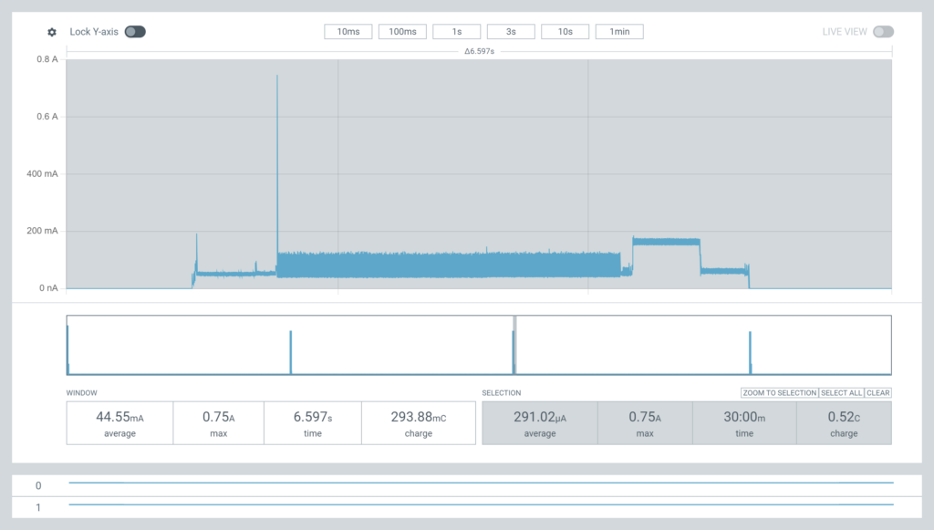
After a few tweaks, I measured an average current draw of around 291µA over a complete 30-minute cycle, including waking, taking the pressure sensor reading, transmitting it over LoRa and returning to deep sleep.
While actually in deep sleep, current draw dropped to around 128µA.
The sensor draws much more current while it is awake, roughly around 180 mA during parts of the measurement and transmission cycle, but it is only awake for a few seconds.
That is the important difference.
For the overwhelming majority of the time, the sensor is asleep.
The firmware shuts down the pressure sensor boost circuit, turns off Wi-Fi, sleeps the LoRa radio, disables unnecessary peripherals and deals with some Heltec-specific hardware that would otherwise continue drawing power.
The sensor also has a solar panel, so I’m not relying entirely on battery capacity.
The 5V solar panel connects directly to the Heltec’s solar input, allowing the board’s onboard charging circuit to keep the 3.7V Li-ion battery topped up.
The goal isn’t to squeeze every possible day out of a battery before manually recharging it. I’d rather have the battery comfortably support the sensor through poor weather and let the solar panel keep topping it back up.
Sending the Reading Over LoRa
Once a measurement has been taken, the sensor needs to get that information back to the LoRa gateway I built previously.
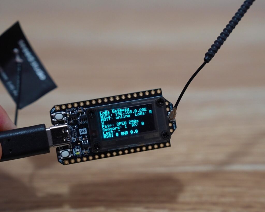
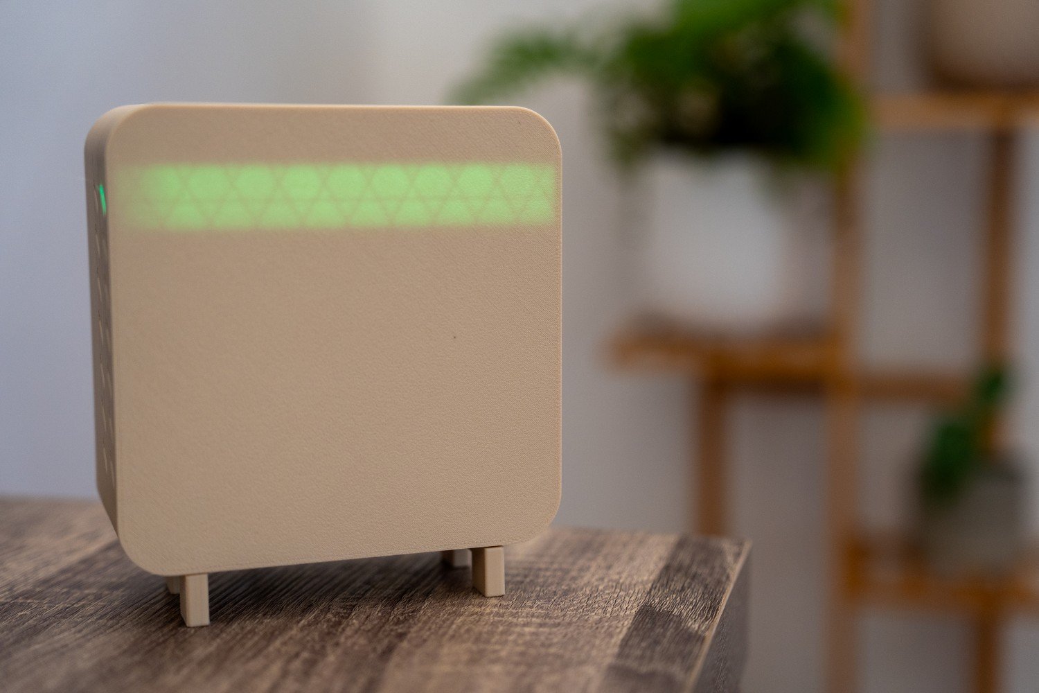
If you haven’t seen that project yet, the gateway is the permanently powered device inside the house that listens for LoRa packets from my remote sensors, then passes that data into Home Assistant through MQTT.
The useful data sent by the tank sensor includes things such as the tank level, water height, derived pressure, pressure sensor status and battery voltage.
The latest version of the protocol doesn’t send this around as plain JSON over the air.
I eventually added a secure protocol around the LoRa communication between the sensor and gateway.
Each sensor has its own identity and cryptographic keys. The payload is encrypted before it is transmitted, and the gateway authenticates the packet before accepting it.
The firmware still uses a NETWORK_ID, which helps separate my LoRa network from another system using compatible radio settings nearby.
For example, someone using the public version of the project could set something like:
constexpr char NETWORK_ID[] = "MY_LORA_NETWORK";One change from my earlier versions is that there is no longer a shared PAIRING_CODE.
Older versions of the project used both a network ID and a pairing code. The latest Secure LoRa v3 setup instead uses unique AES keys provisioned for each sensor and registered with the gateway.
The protocol also uses session IDs and packet counters to help prevent captured packets from simply being replayed later.
You don’t need to understand all of the cryptography to build the sensor, but I wanted the link between the tank sensor and my gateway to be more robust than simply trusting anything that happened to transmit the correct sensor ID.
Pairing the Sensor With the Gateway
I also wanted to avoid manually adding every new sensor to the gateway’s normal runtime configuration.
The gateway has a physical pairing mode.
When pairing is opened on the gateway, an authorised sensor can send a pairing request.
The gateway checks the sensor and its secure credentials. If everything is valid, the sensor is added to the gateway’s saved sensor list and the gateway sends a pairing acknowledgement back.
The sensor saves its paired state locally as well.
After that, normal data transmissions can begin.
The gateway stores its sensor information in non-volatile memory, so restarting it doesn’t mean pairing everything again.
The sensor also has a secure reset/unpair option built into its startup button behaviour if it ever needs to be reprovisioned.
Acknowledgements and Retries
I didn’t want the tank sensor to simply transmit a packet and assume that somebody heard it.
After sending a reading, it switches into receive mode and waits for the gateway to acknowledge the packet.
If the reply isn’t received, the sensor can retry the transmission.
The current firmware allows up to three send attempts, with a small random delay between retries.
This doesn’t guarantee that every individual transmission will make it through, but it makes the system much more tolerant of temporary interference or a missed packet.
It’s also worth noting that the sensor doesn’t immediately decide it has lost its pairing just because it didn’t hear an acknowledgement.
A missing reply could simply mean interference or that the gateway is temporarily offline.
Re-pairing is only triggered when the sensor receives an authenticated response telling it that the gateway no longer recognises its pairing or secure session.
Avoiding Sensors Transmitting at the Same Time
The default reporting interval is around 30 minutes.
The gateway can also return a next_s value in its acknowledgement, allowing it to tell the sensor how long to sleep before the next measurement.
There is still a local 30-minute fallback if the gateway doesn’t provide a valid interval.
I also add a small amount of random jitter to each sleep period.
Instead of every sensor waking at exactly 30 minutes, one might wake slightly before that and another slightly after.
With one sensor this doesn’t really matter, but it becomes useful if you have several devices using the same LoRa channel. You don’t want all of them waking up and trying to transmit at exactly the same instant every half hour.
Getting the Tank Level Into Home Assistant
The tank sensor never talks directly to Home Assistant.
That’s the gateway’s job.
The gateway sits inside the house where it has a permanent power supply and Wi-Fi connection.
When it receives and verifies a LoRa packet, it converts the sensor information into MQTT messages.
The gateway also uses Home Assistant MQTT Discovery, so I don’t need to manually build an MQTT sensor configuration for every reading.
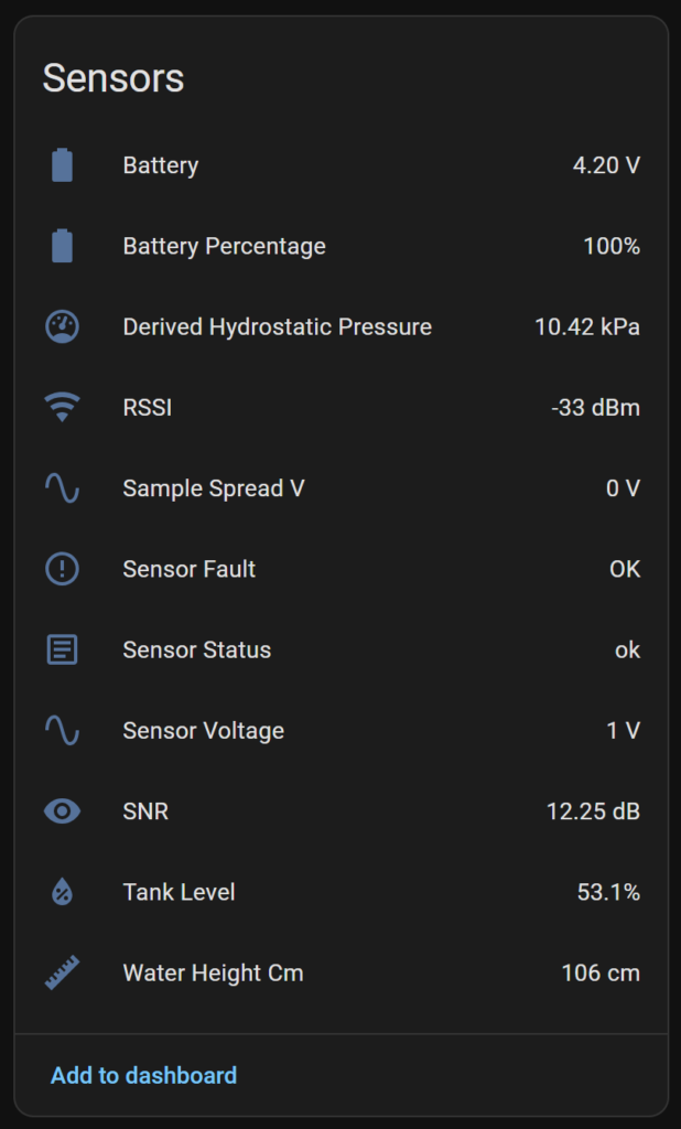
Once the sensor has been paired and starts reporting, Home Assistant can create entities for the data automatically.
For the water tank that includes readings such as tank level, water height, pressure, sensor voltage/status, battery voltage, RSSI, SNR and last-seen information.
This keeps the architecture fairly clean.
Home Assistant doesn’t care whether the remote sensor is using LoRa, Wi-Fi, Zigbee or anything else.
It simply sees MQTT entities coming from the gateway.
It also means the gateway is the only device that needs my Wi-Fi and MQTT credentials.
The tank sensor itself can sit outside with no Wi-Fi connection at all.
Monitoring LoRa Signal Quality
I also publish RSSI and SNR information from the gateway into Home Assistant.
RSSI gives an indication of the received signal strength, while SNR tells me how well the LoRa signal stands out from the surrounding noise.
That makes it much easier to experiment with antenna position and gateway placement instead of guessing whether the link is good.
I also checked the antenna itself with a NanoVNA.
My measurements were approximately 1.3 SWR at 915 MHz, which I’m happy with for this project.
I don’t want to put a specific distance on the project and say it will work over X kilometres because LoRa range depends massively on the installation.
Terrain, buildings, antenna quality, antenna height and radio settings can completely change the result.
What matters to me is that it gives me significantly more useful range for this type of sensor than I was getting from my previous Wi-Fi builds.
Downloading the Code
I’ll be making the tank sensor and gateway code available here so you can use this project as a starting point for your own setup.
COMING SOON
The tank sensor firmware is the part that runs on the battery-powered Heltec at the tank.
The gateway firmware runs on the permanently powered Heltec inside the house and handles LoRa reception, Wi-Fi, MQTT and Home Assistant Discovery.
There are also a few supporting files in the project rather than putting absolutely everything into one enormous Arduino sketch.
TankCalibrationPortal.h contains most of the code responsible for the temporary Wi-Fi calibration interface.
SecureLoRaV3.h handles the secure LoRa protocol.
SecureSensorSecrets.h contains the sensor’s unique security information.
On the gateway side there is a matching secure device registry containing the sensors that are allowed to join.
The gateway also has a config.h file for things such as Wi-Fi and MQTT settings.
The Main Settings You’ll Need to Change
You shouldn’t need to understand every line of the firmware to build your own version.
There are a handful of settings that are much more important.
Each sensor needs a unique ID, for example:
constexpr char SENSOR_ID[] = "tank_01";
constexpr char SENSOR_TYPE[] = "tank";
constexpr char SENSOR_NAME[] = "Rainwater Tank";The sensor and gateway also need to use the same LoRa settings and NETWORK_ID.
Your secure sensor keys need to match the corresponding entry on the gateway.
The downloadable version of the project should use example values rather than my own private keys, so make sure you follow the setup instructions before deploying it.
For most people building this project, I wouldn’t recommend changing all of the radio settings immediately. Get the supplied configuration working first, then experiment later if you actually need to.
Setting Up Your Own Tank
The part you almost certainly will need to change is the calibration.
Every tank and pressure sensor combination is slightly different.
You don’t need to copy my values into your build and hope they’re correct.
Those measurements are specific to my sensor and installation.
Instead, use the calibration portal to record your own sensor at known water depths.
At minimum, I’d want a dry or empty reading and another reliable measurement at a known depth.
Adding more calibration points can improve the conversion across the usable range of the tank.
You’ll also need to enter the usable tank height so the firmware can convert measured water depth into a percentage.
Once that’s saved, the sensor can handle the calculation itself every time it wakes.
What I Like About This Setup
The biggest improvement for me isn’t actually the tank level measurement.
I could already measure the tank with Wi-Fi.
The improvement is everything around it.
The sensor can be placed much further from the house without relying on the home Wi-Fi network. It spends almost all of its time in deep sleep. The solar panel keeps the battery topped up. The pressure sensor only receives power when it is needed.
LoRa transmissions are acknowledged rather than blindly sent, and the radio traffic is encrypted and authenticated.
At the other end, the gateway does all of the work required to turn that remote LoRa packet into normal Home Assistant entities.
It feels much more like a proper remote sensor than my earlier Wi-Fi versions.
Final Thoughts
This project started because I wanted a better way to monitor a rainwater tank that wasn’t close enough to the house for Wi-Fi to be a good solution.
Moving to LoRa solved the main range problem, but it also pushed me to rethink how the rest of the sensor worked.
Reducing the sleep current, switching the pressure sensor power, adding solar power, building a calibration portal, adding acknowledgements and eventually securing the LoRa protocol all made a much bigger difference than simply swapping one radio technology for another.
The end result is a sensor that can spend most of its life asleep, wake every half hour or so, take a tank measurement and send it back to Home Assistant without needing Wi-Fi coverage at the tank.
And because the gateway handles the LoRa side separately from Home Assistant, the tank sensor can stay relatively simple where it matters most: out in the field, running from a battery and doing one job.
Disclaimer: This project is shared for educational purposes only. If you choose to build it, you do so at your own risk. Double-check wiring, follow safety guidelines, and never work on live circuits if you’re unsure.
Some of the links in this post may be affiliate links. If you buy through them, I may earn a small commission at no extra cost to you.
hello jrat
I am really appreciating the detailed explanation and rationale. The low power consumption, longer distance, small packets of data, simplicity and security are really critical to me. There’s clearly been a lot of thought and time put into this project. Thank you for that, it doesn’t go unnoticed.
Of particular note “ I wanted the link between the tank sensor and my gateway to be more robust than simply trusting anything that happened to transmit the correct sensor ID”. Critical! It puts my thoughts at ease that came upon reading the first part. I have been thinking a lot about all of the home devices/cameras/etc sending their packets to an unknown IP in some opaque country.
Looking forward to the code drop.