
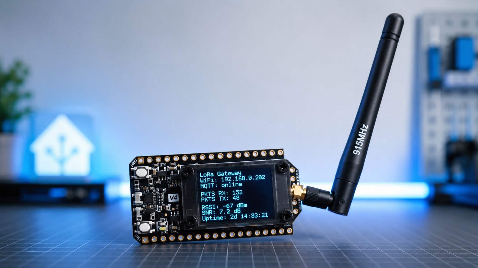
If you want to monitor things around your home, garden, shed, or property without relying on Wi-Fi at every sensor location, a LoRa gateway is a really useful place to start.
For my setup, the gateway is the middle point between my remote sensors and Home Assistant.
The sensors send small packets of data over LoRa. The gateway receives those packets, connects to Wi-Fi, and then sends the data into Home Assistant using MQTT.
This guide covers how I set up a simple private LoRa gateway using the Heltec WiFi LoRa 32 V4. This is not a LoRaWAN gateway. It is a custom LoRa setup for my own DIY sensors, such as a compost thermometer, a water tank sensor, or any other low-data sensor around the property.
The goal is to build one gateway first, then use that same gateway for multiple sensors later.
Looking for the latest version?
I have since developed a newer version of this gateway with per-device AES encryption and improved sensor authentication. If you want the more secure version used in my latest water tank sensor project, you can find that here.This article covers the original, simpler gateway design shown in the YouTube video.
What this project does
This gateway receives LoRa packets from remote sensor nodes and publishes the received data to MQTT so Home Assistant can use it.
The basic flow looks like this:
Sensor node → LoRa → Gateway → MQTT → Home AssistantA sensor wakes up, takes a reading, sends a small packet over LoRa, and waits for a reply.
The gateway receives the packet, checks that the sensor is allowed to talk to it, sends back an acknowledgement, and then publishes the data to MQTT.
This means each sensor does not need Wi-Fi. The sensors only need LoRa, and the gateway handles the Wi-Fi and Home Assistant side of things.
That is especially useful for outdoor sensors, battery-powered sensors, or sensors located too far away from the house for reliable Wi-Fi.
This is not LoRaWAN
This project does not use LoRaWAN.
LoRaWAN is a more formal network system with gateways, network servers, device activation, and a proper LoRaWAN packet structure. That is great for some use cases, but it also adds more complexity.
For this project, I wanted something simpler.
This is a private LoRa network for my own sensors. The sensors and the gateway use the same packet format, network name, and pairing system. The gateway receives packets directly and sends the data to MQTT.
For a small DIY sensor network around the house or property, this keeps things easier to understand and easier to modify.
Hardware used
For the gateway, I am using the Heltec WiFi LoRa 32 V4.
This board is a good fit because it already includes:
- ESP32 microcontroller
- SX1262 LoRa radio
- Wi-Fi
- USB-C
- Small OLED display
- Antenna connector
Because the LoRa radio and OLED are already built into the board, the gateway hardware is quite simple. I do not need to wire a separate LoRa module to an ESP32 just to get the gateway working.
For the antenna, I am using a larger 915 MHz antenna instead of only relying on the small antenna that comes with the board.
For testing on the bench, the smaller antenna is usually fine. But because this gateway will eventually need to receive data from sensors outside, I wanted to give it the best chance of having a reliable signal.
Parts used
- Heltec WiFi LoRa 32 V4
- 915 MHz antenna
- USB-C data cable
- Computer with VS Code and PlatformIO installed
- MQTT broker, such as Mosquitto
- Home Assistant
- Test LoRa sensor node
Heltec V4
A good pick for builds if you want a compact LoRa board with an OLED screen, Wi-Fi and USB-C.
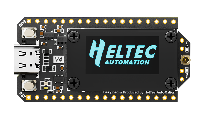
For the test sender, I am using a Seeed XIAO ESP32-C6 with a Wio-SX1262 LoRa module. This is not the final water tank sensor. It is just a simple test node that sends demo data so I can confirm the gateway is working.
You can use other boards for the sensor node, but you will need to adjust the code and pinout to match your hardware.
Choosing the correct LoRa frequency
Make sure you use the correct LoRa frequency for your region.
I am in Australia, so I am using 915 MHz hardware and 915 MHz settings.
If you are in another region, your frequency may be different. You need to make sure the gateway, antenna, and sensor nodes all match the frequency band you are using.
The important thing is that the gateway and sensors must be using the same LoRa frequency and compatible LoRa settings.
Why this board uses the SX1262 radio
The Heltec WiFi LoRa 32 V4 uses the SX1262 LoRa radio.
The SX1262 is a good fit for this type of DIY sensor network because it is designed for long-range, low-power communication. It is well suited to sensors that only need to send small amounts of data every now and then.
One thing to understand is that the SX1262 is half duplex.
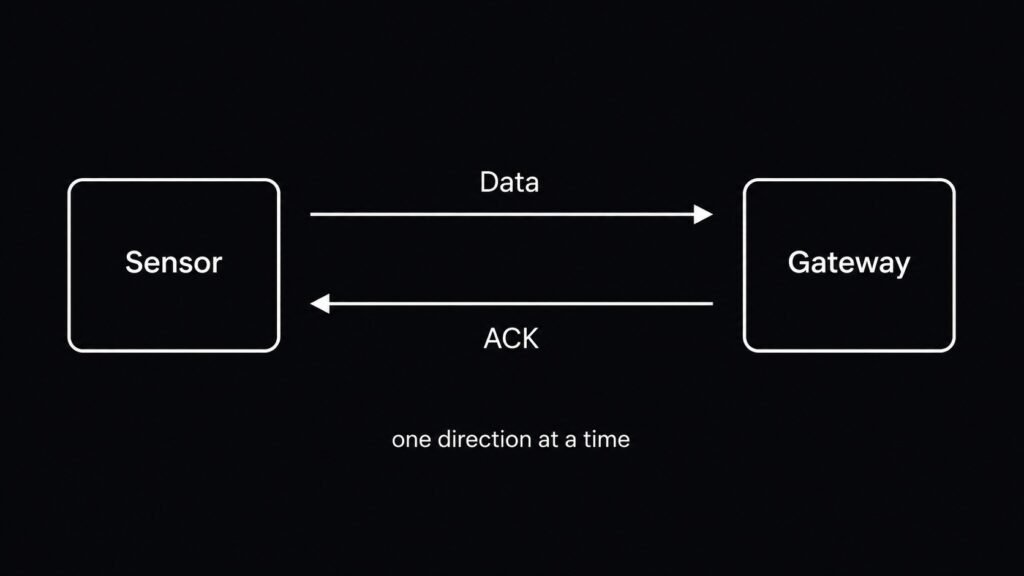
That means it can transmit or receive, but it cannot do both at the exact same time.
For this project, that is not really a problem.
The sensor sends a packet. The gateway receives it. Then the gateway sends a quick acknowledgement back. The gateway does not need to transmit and receive at the exact same moment.
As I add more sensors, I will also make sure the sensor code sends readings at slightly random times. That way, every sensor is not trying to transmit at exactly the same second.
For example, if two sensors are set to report about every 15 minutes, each sensor can add a small random offset. This helps reduce packet clashes and should make the network more reliable.
For a few DIY sensors, this setup is a good balance between range, cost, and complexity.
How the gateway works
The gateway has a few main jobs:
- Connect to Wi-Fi
- Connect to MQTT
- Listen for LoRa packets
- Check whether a sensor is paired
- Accept valid packets
- Reject unknown or invalid packets
- Send an acknowledgement back to the sensor
- Publish data to MQTT
- Provide Home Assistant MQTT discovery entities
Once it is running, the gateway stays in receive mode and waits for sensor packets.
When a packet arrives, the gateway checks whether it belongs to the correct network and whether the sensor is allowed to talk to the gateway.
If the packet is accepted, the gateway publishes the data to MQTT and sends an ACK reply back to the sensor.
The ACK reply tells the sensor that the packet was received successfully. It can also include the next sleep time, which is useful for battery-powered sensors.
Software required
To install the gateway code, you will need:
- VS Code
- PlatformIO extension
- The gateway code
- A USB data cable
- MQTT broker details
- Wi-Fi details
The gateway project is built and uploaded using PlatformIO.
The test sensor node I am using is programmed separately in the Arduino IDE, but the gateway itself uses VS Code and PlatformIO.
Opening the gateway project
Once you have downloaded the gateway code, open the project folder in VS Code.
If the project opens properly, you should see the normal PlatformIO project structure.
The project should include files such as:
platformio.ini
src/
include/
config.hThe main file you will need to edit is:
config.hThis is where you add your own Wi-Fi, MQTT, LoRa, and pairing settings.
Editing config.h
Before uploading the gateway code, open config.h and update it to match your own setup.
The main things to check are:
- Wi-Fi SSID
- Wi-Fi password
- MQTT host
- MQTT port
- MQTT username
- MQTT password
- LoRa frequency
- Network name
- Pairing code
- Gateway name or gateway ID
For my setup, I am using 915 MHz and a private network name for my own LoRa sensors.
// -------------------- Wi-Fi --------------------
#define WIFI_SSID       "YOUR_WIFI_NAME"
#define WIFI_PASSWORD   "YOUR_WIFI_PASSWORD"

// -------------------- MQTT --------------------
// Home Assistant MQTT broker. Usually your HA IP address.
#define MQTT_HOST       "192.168.1.10"
#define MQTT_PORT       1883

// Leave blank if your broker does not need auth.
#define MQTT_USER       ""
#define MQTT_PASSWORD   ""

// Base topic used by the gateway.
#define MQTT_BASE_TOPIC "home/lora_gateway"

// Home Assistant discovery prefix. Usually "homeassistant".
#define HA_DISCOVERY_PREFIX "homeassistant"

// -------------------- LoRa radio --------------------
// Australia 902-928 MHz hardware: keep all sensors on the exact same settings.
// Start with SF8/BW125. Increase SF to 9/10 later only if range is poor.
#define LORA_FREQ_MHZ       915.0
#define LORA_BW_KHZ         125.0
#define LORA_SF             8
#define LORA_CR             5
#define LORA_SYNC_WORD      0x12
#define LORA_TX_POWER_DBM   17
#define LORA_PREAMBLE_LEN   8

// Must match every sensor. This is not encryption; it just rejects unrelated packets.
#define NETWORK_ID          "JRAT_LORA_HOME"

// -------------------- Pairing security --------------------
// Sensors must include this code in their PAIR_REQ packet.
// This is not full encryption, but it stops accidental/random pairing.
#define PAIRING_CODE "CHANGE_ME_PAIR_CODE"The exact code will depend on the version of the project you are using, but the idea is the same.
The Wi-Fi settings allow the ESP32 to connect to your home network.
The MQTT settings allow the gateway to send data to your MQTT broker.
The LoRa settings make sure the gateway is listening on the same frequency and network as your sensors.
The pairing code is used when adding new sensors. This helps stop random packets from being accepted as new devices.
Uploading the gateway code to the Heltec V4
Once the config file is updated, plug the Heltec WiFi LoRa 32 V4 into your computer using a USB-C data cable.
In VS Code, open the PlatformIO tab.
First, build the project to make sure there are no errors.
Then upload it to the board.
The basic process is:
Build → Upload → Open Serial MonitorIf the board does not upload straight away, you may need to put it into bootloader mode.
On the Heltec board, you can usually do this by:
- Holding the BOOT button
- Tapping RESET
- Releasing BOOT
- Uploading again
Once the upload is finished, open the serial monitor.
You should see the gateway booting up, connecting to Wi-Fi, connecting to MQTT, and then starting to listen for LoRa packets.
What you should see in the serial monitor
When the gateway starts correctly, the serial monitor should show the main startup steps.
You should see things like:
- Gateway starting
- Wi-Fi connection attempt
- Wi-Fi connected
- MQTT connection attempt
- MQTT connected
- Known sensor count
- LoRa receive mode
- Incoming packets when sensors transmit
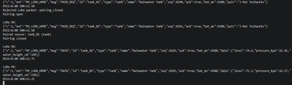
The serial monitor is very useful while setting everything up because it shows what the gateway is doing in real time.
Once the gateway is mounted permanently, you probably will not keep the serial monitor open. That is where the OLED display becomes useful.
OLED display overview
The Heltec board includes a small OLED display.
This is useful because it gives you a quick status check without needing to plug the gateway into your computer.
The OLED can show things like:
- Gateway name
- Wi-Fi status
- MQTT status
- LoRa receive status
- Pairing mode open or closed
- Number of known sensors
- Number of received packets
- Last sensor ID
- RSSI from the last packet
- SNR from the last packet
This makes the gateway much easier to check once it is installed.
For example, if the gateway is mounted inside the house, you can quickly look at the screen and see whether it is online, connected to MQTT, and receiving packets.
MQTT and Home Assistant setup
For this project, I am assuming you already have MQTT working in Home Assistant.
I am using Mosquitto as the MQTT broker.
The important thing is that the MQTT details in the gateway config must match your MQTT broker details.
You will need to check:
- MQTT server address
- MQTT port
- MQTT username
- MQTT password
Once the gateway connects to MQTT, it publishes its own status and state.
For example, the gateway might publish to topics like:
home/lora_gateway/status
home/lora_gateway/state
The exact topic structure can be changed in the code, but the idea is that the gateway has its own MQTT topics for status, state, and sensor data.
Home Assistant MQTT discovery
The gateway also uses MQTT discovery.
This allows Home Assistant to automatically create entities for the gateway without you manually adding each one.
For example, Home Assistant can create entities for:
- Gateway status
- Gateway uptime
- Known sensor count
- Received packet count
- ACK packet count
- Rejected packet count
- Wi-Fi RSSI
This makes it much easier to monitor the gateway from Home Assistant.
Instead of only seeing the final sensor readings, you can also see whether the gateway itself is healthy.
That is useful because if a sensor stops updating, you can check whether the gateway is still online, whether packets are being received, and whether any packets are being rejected.
Testing the gateway with a sensor node
To test the gateway, I am using a simple LoRa sender node.
This test node is not the final water tank sensor. It is just sending demo tank data so I can prove that the full communication path is working.
The test setup is:
XIAO ESP32-C6 + Wio-SX1262 LoRa moduleThe test node sends a packet over LoRa.
The gateway receives that packet.
The gateway publishes the data to MQTT.
Home Assistant can then use the MQTT data.
This proves the full path is working before I start building the final outdoor sensors.
What the test packet includes
The test sender transmits a structured packet.
The packet includes information such as:
- Network name
- Message type
- Sensor ID
- Sensor type
- Sensor name
- Sequence number
- Battery reading
- Sensor data
For example, a test water tank packet might use:
Sensor ID: tank_01
Sensor type: tank
Sensor name: Rainwater Tank
The sensor data might include:
- Demo water level
- Pressure reading
- Water height
- Battery voltage or percentage
{
  "network": "YOUR_NETWORK_NAME",
  "type": "data",
  "id": "tank_01",
  "sensor_type": "tank",
  "name": "Rainwater Tank",
  "seq": 1,
  "battery": 4.1,
  "data": {
    "level": 75,
    "pressure": 12.3,
    "height": 1.2
  }
}This example is not connected to the final pressure sensor yet, but it proves the important part.
The sensor sends data over LoRa, the gateway receives it, and the gateway can send that data into Home Assistant.
ACK replies
After the gateway receives a valid packet, it sends an ACK reply back to the sensor.
ACK simply means acknowledgement.
It tells the sensor that the packet was received successfully.
This is useful because the sensor does not have to guess whether the gateway received the message.
The ACK reply can also include the next sleep time.
For example:
next_s: 900That means the sensor can wait 900 seconds before sending again.
900 seconds is 15 minutes.
This will be especially useful for battery-powered sensors because the sensor can wake up, send data, receive confirmation, and then go back to sleep.
That keeps the sensor awake for as little time as possible, which helps save power.
Pairing new sensors
By default, the gateway does not accept every new sensor.
During normal use, pairing is closed.
To add a new sensor, you open pairing mode on the gateway.
On my setup, pressing the BOOT button on the Heltec V4 opens pairing mode.
Once pairing mode is open, the new sensor can send a pairing request.
The gateway checks that the sensor is using the correct network name and pairing code.
If the details match, the gateway saves that sensor.
After the sensor is paired, it does not need to pair again every time it sends data. The gateway remembers it, even after a reboot.
The normal process is:
Press BOOT on gateway → Pairing opens → Sensor sends pairing request → Gateway saves sensorOnce paired, the sensor can send normal data packets.
Clearing paired sensors
While testing, it is useful to be able to clear the saved sensors and start again.
On my gateway, holding the BOOT button for about 10 seconds clears the saved sensor list.
This is handy if:
- You change a sensor ID
- You want to reset the gateway
- You are testing different sensor nodes
- You want to remove old devices
Once everything is installed permanently, this probably will not be needed very often. But while developing the project, it is a useful feature to have built in.
How multiple sensors will work
The reason I am building the gateway first is so I do not need a separate receiver for every sensor.
Each sensor has its own ID and type.
For example:
tank_01      → water tank sensor
weather_01   → weather sensor
tank_02      → second water tank sensor
weather_02   → weather sensor
All of these sensors can send data to the same gateway.
The gateway just needs to know which sensors are paired.
Each packet tells the gateway what sensor it came from and what type of data it contains.
This means the same gateway can become the backbone for a full DIY sensor network.
Avoiding clashes between sensors
Because this is a simple LoRa network, I do not want every sensor transmitting at the exact same time.
If multiple sensors all wake up on the same schedule and transmit at the same second, packets could clash.
To reduce the chance of this happening, the sensor code can add a small random delay.
For example, instead of every sensor sending exactly every 15 minutes, each sensor can send roughly every 15 minutes with a small random offset.
That might look something like:
Sensor 1 sends after 15 minutes and 12 seconds
Sensor 2 sends after 14 minutes and 47 seconds
Sensor 3 sends after 15 minutes and 31 seconds
That small difference helps spread out transmissions.
For a few DIY sensors around the house, this should be enough to make the system much more reliable.
What this gateway proves
At this stage, the gateway is doing everything I need it to do.
It can:
- Connect to Wi-Fi
- Connect to MQTT
- Listen for LoRa packets
- Pair new sensors
- Remember paired sensors
- Reject unknown sensors
- Send ACK replies
- Publish data to MQTT
- Create Home Assistant entities using MQTT discovery
The demo data itself is not the most important part yet.
The important thing is that the full communication path works from end to end.
Sensor → LoRa → Gateway → MQTT → Home AssistantNow I have a gateway that can sit inside the house and receive data from different LoRa sensors around the property.
Troubleshooting
The board will not upload
Make sure you are using a USB data cable, not a charge-only cable.
If the upload still fails, try putting the board into bootloader mode:
- Hold BOOT
- Tap RESET
- Release BOOT
- Upload again
Also make sure PlatformIO is set up correctly and the correct board is selected in the project.
The gateway does not connect to Wi-Fi
Check your Wi-Fi SSID and password in config.h.
Also make sure the gateway is within range of your Wi-Fi network.
If your network uses separate 2.4 GHz and 5 GHz names, make sure the ESP32 is connecting to the 2.4 GHz Wi-Fi network.
The gateway does not connect to MQTT
Check the MQTT host, port, username, and password.
If you are using Mosquitto in Home Assistant, make sure the user details match what you entered in the gateway config.
Also check that MQTT is running and that Home Assistant can connect to it.
No Home Assistant entities appear
Make sure MQTT discovery is enabled in Home Assistant.
Also check the gateway serial monitor to confirm that it is connected to MQTT.
If MQTT is connected but entities are not appearing, check the discovery topic structure in the code.
The gateway does not receive LoRa packets
Check that the gateway and sensor are using the same:
- Frequency
- Network name
- LoRa settings
- Packet format
Also make sure the antennas are connected properly.
Do not run LoRa boards without an antenna connected, especially when transmitting.
The sensor is rejected
If a sensor is rejected, pairing may be closed or the sensor may not be using the correct pairing code.
Open pairing mode on the gateway and try again.
Also check that the sensor ID, network name, and pairing code are correct.
Packets are unreliable
If packets are unreliable, try moving the gateway, improving the antenna position, or using a better antenna.
Also avoid placing the gateway right beside large metal objects, inside metal enclosures, or directly behind equipment that could block the signal.
As more sensors are added, make sure they use slightly random send times so they do not all transmit at once.
Where this project goes next
This gateway is the first step.
Once the gateway is working, I can start building the actual sensors that will use it.
The long-term goal is to have one simple LoRa gateway inside the house and multiple low-power LoRa sensors around the property.
That way, I can monitor things like water tank levels, weather data, or other outdoor sensors without needing Wi-Fi at every location.


Good Morning.
This gateway looks brilliant.
Have you shared any sensor projects that connect to it yet ?
Or can you share some sample code to write code for my own sensors perhaps ?
I would like to build a plant moisture sensor using a capacitive sensor.
Regards Dave
Thanks Dave, I appreciate it. I have a new blog post out that walks through setting up a water tank sensor to the LoRa gateway. The gateway code has been updated from this project, but I’m hoping it’s still fairly simple for others to set up themselves!
Hello to DownUnder,
Top, running on my Heltec v3 too after 5 mins work :O). Now waiting for the sensor :O).
Best regards from the Caribbean, Northcoast of the Dominican Republic, Holger
Hi,
Do you have the sensor working on v3 as well?
Thanks
platform.ini for Heltec V3:
[env:heltec_wifi_lora_32_V3]
platform = espressif32
board = heltec_wifi_lora_32_V3
framework = arduino
; Heltec’s V4 PlatformIO docs currently use a local board + variant definition.
board_build.variants_dir = variants
board_build.variant = heltec_V3
monitor_speed = 115200
upload_speed = 921600
monitor_dtr = 0
monitor_rts = 0
# Behebt Suchfehler bei verschachtelten Bibliotheken (SPI/I2C)
lib_ldf_mode = deep+
# Zwingt den Compiler auf Linux, den korrekten V3-Pin-Pfad zu nutzen
build_flags =
-D CORE_DEBUG_LEVEL=0
-I${sysenv.HOME}/.platformio/packages/framework-arduinoespressif32/variants/heltec_wifi_lora_32_V3
lib_deps =
ropg/Heltec_ESP32_LoRa_v3
jgromes/RadioLib
knolleary/PubSubClient@^2.8
bblanchon/ArduinoJson@^6.21.5
adafruit/Adafruit SSD1306@^2.5.10
adafruit/Adafruit GFX Library@^1.11.9
first to lines:
[platformio]
default_envs = heltec_wifi_lora_32_V3