TL;DR
- A CN3791 board is a switch-mode (buck) solar charger for one 3.7V Li-ion/LiPo cell (4.2V full).
- “MPPT” on these boards usually means holding the panel near a set voltage using a resistor divider. It is not the same as a big solar controller.
- Boards vary a lot by vendor. Input range, max charge current, MPPT setpoint, LED behaviour, and protections can all differ.
- Most cheap modules do not include proper load sharing (power-path). That matters if you run your device while charging.
- Assume you still need battery protection / low-voltage cut-off somewhere in the system.
Quick Summary
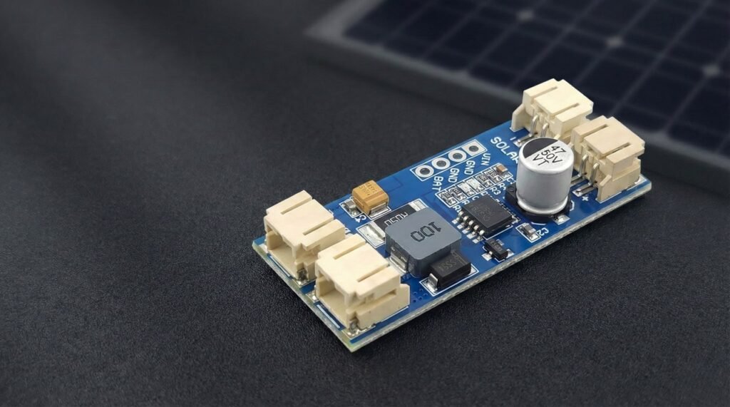
A CN3791 MPPT board is a small module built around the CN3791 lithium battery charger IC. It is designed to charge a single-cell Li-ion or LiPo battery from a solar panel (or another DC source), while trying to keep the panel operating near its “sweet spot” for power.
Use it when
- You want a simple way to charge one 3.7V cell from a small panel.
- Efficiency matters (you do not want to burn heaps of power as heat like a basic linear charger).
- Your project can tolerate that the “MPPT” behaviour is usually a fixed setpoint, not a fully dynamic tracker.
If you’re building a small 1S lithium project, this is the CN3791 board I’d suggest starting with.
CN3791
A low-cost solar lithium battery charger module that works well for small DIY battery projects when paired with the right solar panel and protection circuit.
Avoid it when
- You need to charge anything other than 1S lithium (no LiFePO4, no 2S packs).
- Your load is always-on and critical, and you need a stable “system output” while charging. Many CN3791 boards are chargers only.
- You need strong, guaranteed protections built in (reverse polarity, short circuit, battery undervoltage cut-off). Many modules do not provide all of these.
Safety disclaimer
Lithium batteries can be dangerous if shorted, overcharged, physically damaged, or used without proper protection. Double-check polarity and wiring, fuse the battery if you can, and do your first tests somewhere safe. Always read the datasheet of the module you are connecting.
What does MPPT mean?
Solar panels do not behave like a normal power supply.
A panel has an open-circuit voltage (Voc) when nothing is connected, but when you draw current the voltage drops. The panel makes the most power at a particular operating point called the maximum power point. That point shifts with sunlight and temperature, but it is usually “around” a target voltage.
What CN3791-type “MPPT boards” typically do is constant-voltage MPPT:
- The charger aims to keep the panel near a set target voltage (often set by a resistor divider on the board).
- If the panel voltage collapses, the charger backs off.
- If the panel has headroom, the charger pulls more current (up to its charge current limit).
This is different to a basic USB LiPo charger (common TP4056 boards):
- Many basic chargers are linear and waste extra voltage as heat.
- They usually do not try to hold a panel at a sensible operating voltage.
- They can behave badly on solar because they pull current until the panel sags, then everything chatters.
CN3791 is a switch-mode buck charger, so it can convert excess input voltage into charging current more efficiently, and it can be friendlier to a panel.
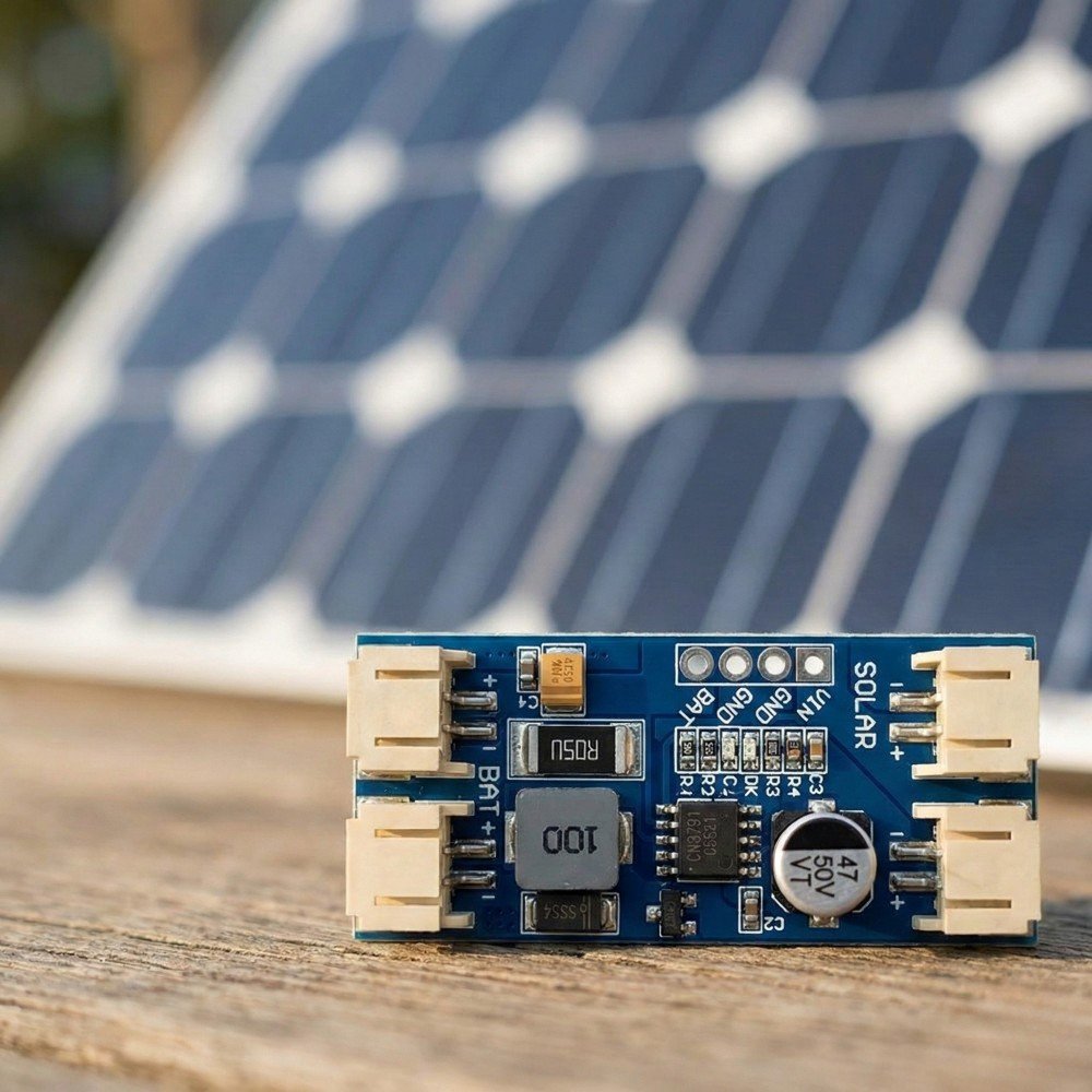
Wiring
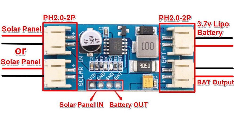
Most CN3791 modules you buy online expose two main connections:
- Solar input: usually marked VIN+/VIN-, or SOL+/SOL-
- Battery: usually marked BAT+/BAT-, or B+/B-
Typical wiring
- Solar panel positive → VIN+
- Solar panel negative → VIN-
- Battery positive → BAT+
- Battery negative → BAT-
That is the charger portion.
Where does the load go?
This depends on the board design.
Many cheap CN3791 boards do not include ideal load sharing (also called power-path). In that case:
- There is no separate “load output”.
- Your device is usually connected to the battery (often through a regulator).
Why that matters
- The charger may not terminate correctly if your device is drawing current while charging.
- Your load current is mixed with charge current, so what the charger “sees” is not clean.
- At night your device runs only on the battery, so you need to plan for brownouts.
What to check on your specific module
Because vendors change layouts and features, treat these as a checklist:
- Are there pads labelled OUT, LOAD, SYS, 5V, or similar?
- Does the listing explicitly say power-path or load sharing?
- Are there extra MOSFETs and a separate output stage, or is it just charger parts?
If you cannot confirm power-path exists, assume it does not.
Choosing a Solar Panel
Panel selection is where most solar node builds succeed or fail.
The basics (voltage, current, watts)
- Voltage is the “push”.
- Current is what can flow.
- Watts (W) = Volts (V) × Amps (A).
Solar panel specs usually include:
- Voc: open-circuit voltage (no load)
- Vmp: voltage at maximum power (under load)
- Isc/Imp: current short-circuit / current at max power
The charger cares about what the panel can supply under load, not what it shows open circuit.
6V panels as a common example
Small “6 V” panels are popular for hobby nodes because they are cheap and easy to mount.
What to watch for:
- Some “6 V” panels have a Vmp around 5 to 6V, and a Voc higher than that.
- If your CN3791 board’s MPPT target is set too high (for a “12V panel version”), a 6V panel might never sit at the right operating point and charging will be weak.
Rule of thumb
Match the board’s intended panel range (or MPPT setpoint) to your panel. If the listing says “12V version”, do not assume it works well with a 6V panel unless it is adjustable or confirmed.
“Higher watts” does not force power into the circuit
A larger panel does not “push” extra watts into your charger automatically.
A panel can only deliver what the charger draws. If the charger can only use a couple of watts (because of current limits or battery state), the rest is simply unused.
What a larger panel does give you:
- Better charging in cloudy weather
- Better charging in winter sun
- More margin for dirt, heat, and partial shade
Panel checklist
- Input voltage safety: confirm the panel Voc will not exceed the board’s input rating. If you cannot verify the board rating, do not gamble.
- Match Vmp to the MPPT target (or buy a module where you can adjust MPPT).
- Keep panel wiring short and reasonably thick, especially for 6V panels.
Battery Compatibility
CN3791 boards are for single-cell (1S) lithium:
- Li-ion (like 18650)
- LiPo pouch packs
They charge to 4.2V (standard Li-ion/LiPo full charge voltage).
Common capacity ranges
Capacity is not a compatibility issue, but it changes run time and charge time.
Typical ranges people use:
- 500 mAh to 5000 mAh LiPo pouches
- 2000 mAh to 3500 mAh 18650 cells (varies by brand)
Battery quality matters
With cheap cells, the label can be fantasy. If your node is remote, do not cheap out on the battery.
Protection expectations
Many CN3791 boards are chargers only. They often do not include:
- battery undervoltage cut-off (overdischarge protection)
- short-circuit protection
- overcurrent protection
So plan to use:
- a protected 18650, or
- a battery pack that already includes protection, or
- a separate 1S protection/BMS board
If you cannot confirm protection exists, assume it does not.
Heat and Current Limits
This is the area where “CN3791 board” can mean very different things.
The CN3791 IC can support high charge current on paper, but the module is limited by:
- inductor size and saturation
- current sense resistor value (sets charge current)
- diode or synchronous switch design
- PCB copper area and thermal layout
- airflow and enclosure temperature
Why these boards get hot
- High charge current for long periods
- High input voltage relative to battery
- Sealed enclosures sitting in the sun
- Dark boxes, no airflow, no thermal path
Tips to keep temps down
- Mount the board with some air gap. Avoid foam tape that insulates it.
- Do not mount it hard against the wall of a sun-facing enclosure.
- If your enclosure is IP rated and sealed, consider a larger box so air volume helps.
- If it runs hot in testing, reduce charge current (if your module allows it), or pick a board designed for higher power.
When to pick a different approach
If you need reliable high current, stable system output, or you are charging a big cell from a big panel in summer heat, it can be smarter to use:
- a higher quality charger module with known thermal performance, or
- a charger with proper power-path and protections, or
- a small solar charge controller matched to your battery chemistry
Protection and Safety
This is the part where you need to be picky and a bit paranoid.
What the IC usually provides
The CN3791 IC includes charge control logic and common charger protections (for charging behaviour). The exact list depends on the datasheet.
What modules often do not provide
This varies by vendor and board layout. Common missing protections include:
- reverse polarity protection on VIN and BAT
- battery undervoltage cut-off (overdischarge protection)
- short-circuit protection at the output
- a fuse
Safety checklist
Use this before you deploy anything remote:
Wiring and setup
- Confirm polarity with a multimeter before connecting the battery.
- Add a small fuse on battery positive close to the battery.
- Use proper strain relief so vibration does not rip pads off.
Battery
- Use a known brand cell or a reputable pack.
- Use a protected cell or separate 1S protection board if needed.
- Do not use swollen or damaged LiPo packs.
Enclosure
- Keep the charger away from flammable materials.
- Avoid trapping the charger against insulation or foam.
- Do a heat test in the sun before you trust it.
Real-World Gotchas
USB-C solar panels
Some small panels with USB-C are actually “phone charger panels”. They might include:
- a 5V regulator
- auto shutoff if current is too low
- pulsing behaviour in weak light
That can make charging unstable.
What to do
- Measure the output under load.
- If possible, test with the CN3791 board connected and watch voltage stability.
- If it pulses on and off, consider a different panel or a different front-end.
Long cable voltage drop
Long thin cables can drop enough voltage to stop charging, especially with 6V panels.
Fixes:
- Shorter cable
- Thicker cable
- Higher voltage panel (only if within board limits and MPPT is set appropriately)
Cloud and shade
In cloud, you may still see a reasonable open-circuit voltage, but the panel cannot supply current. The charger may start then back off repeatedly.
Startup and dusk behaviour
At dawn and dusk, voltage can hover around the minimum required for charging. That can look like:
- LEDs flickering
- charge current coming and going
- your device rebooting if power is marginal
Night reboots
Common causes:
- battery voltage sag under Wi-Fi or radio bursts
- poor regulator choice
- no battery protection cut-off (battery dips too low)
- the project draws more at night than you estimated
Fixes:
- reduce load, use deep sleep, and lower transmit frequency
- use a regulator that can handle peak current
- add bulk capacitance where it matters
- increase battery capacity or panel size
Troubleshooting
Here’s a practical symptom list that covers most issues.
| Symptom | Likely cause | What to check |
|---|---|---|
| Battery never charges | Wrong wiring, not enough panel voltage under load, board is “12V version” with 6V panel | Measure panel voltage at VIN while connected, confirm polarity, confirm board version |
| Charging is very slow | Panel too small, poor sun angle, MPPT setpoint mismatch | Try full sun test, compare Vmp to board’s intended panel range |
| LEDs flicker | Weak light, panel pulsing, cable drop | Shorten cable, test different panel, measure VIN stability |
| Board gets too hot to touch | Too much charge current for that module, poor airflow | Reduce current if possible, improve mounting airflow, choose a higher-rated module |
| Device reboots when radio transmits | Regulator dropouts, battery sag, poor wiring | Add bulk capacitance, use thicker wiring, better regulator, reduce transmit power/duty cycle |
| Battery “full” too early | Load current confusing charge termination | Test charging with the load disconnected, or use a power-path charger |
| Works in sun but dies overnight | Battery too small, overdischarge, load too high | Increase capacity, reduce power draw, add battery protection/LVC |
A few fast multimeter tests
- Panel open circuit: check Voc. Useful to confirm the panel is not dead.
- Panel under load: measure VIN while charging. This is the real test.
- Battery voltage: check battery at dusk and before dawn to see how low it gets.
- Cable drop: measure at the panel and at VIN to see how much is lost in wiring.
FAQ
Can CN3791 charge LiFePO4?
No. CN3791 boards are intended for 1S Li-ion/LiPo (4.2V full charge).
Can I use two cells in series (2S)?
No. You need a 2S charger and balancing, which is a different setup.
Is CN3791 “real MPPT”?
It is usually a fixed voltage MPPT approach. It aims to hold the panel near a setpoint, not constantly sweep and hunt like big controllers.
Why do listings mention 6V, 9V, 12V, 18V?
Many boards are built with different MPPT divider values. Pick one matched to your panel or confirm it is adjustable.
Will a bigger watt panel damage the charger?
Not by forcing watts. The charger draws what it can. The real risk is exceeding input voltage limits or overheating at high current.
Do CN3791 boards have load sharing?
Many do not. If you cannot confirm power-path exists, assume the load is just tied to the battery and plan for that.
Do I need a battery protection board?
Often yes. Many CN3791 modules do not provide overdischarge or short circuit protection.
Why does the charging light flicker in cloud?
The panel may not be able to supply stable current. Voltage sags, the charger backs off, and it repeats.
Can I use a USB-C solar panel?
Sometimes. Measure it under load. Some USB-C panels regulate to 5V or pulse on and off in weak light.
Why does my node reboot at night?
Battery voltage sag, poor regulator choice, or the battery is getting too low. Reduce load, use deep sleep, and add proper battery protection.
Some of the links in this post may be affiliate links. If you buy through them, I may earn a small commission at no extra cost to you.


